1 - ESP-IDF getting started
Programming native applications on the Badge requires an ESP
IDF to
be installed. IDF stands for “IoT Development Framework” and is Expressif’s
SDK which provides:
- convenient access to hardware functionality
- implementation of protocols such as TLS, HTTP and MQTT which are
commonly used in IoT projects
- common utilities such as logging, error handling and JSON parsing
- infrastructure code for building, flashing and debugging.
The IDF will be installed automatically (via git submodules and make commands which we
will point out) but it does require some dependencies to be installed.
Installing Prerequisites
How to install these prerequisites is described on the IDF documenttion page for:
The instructions will (mainly) install git, cmake and python. Remember you DO
NOT have to install the IDF!
In order to sideload the apps you develop, you will be using our webusb
tools. These tools will get
automatically installed, but require pyusb to be installed. This can be
installed with pip install pyusb or apt install python3-usb
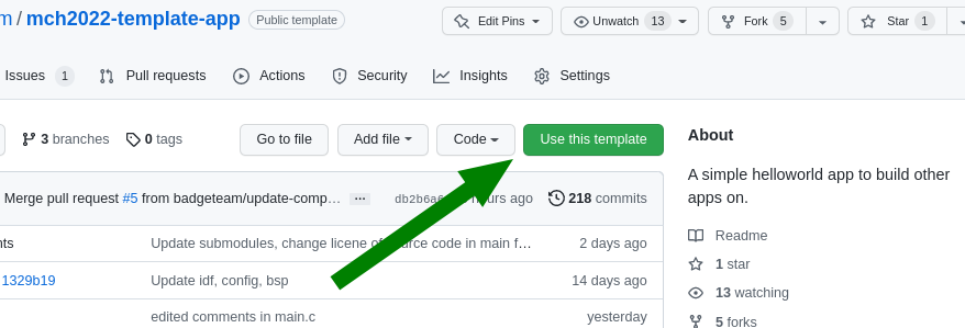
Download & build the “template app”
We created a basic Hello World template
app that’s intended to be
used as a basis for native badge apps you build. To allow you to get started quickly, the
template app downloads the IDF in the required version, as well as some badge
specific components you will.
To clone the template app, open a shell:
$ git clone https://github.com/badgeteam/mch2022-template-app my_fancy_app_name
$ cd my_fancy_app_name
The
Makefile
in the template app contains a number of targets for your convenience:
prepare : Download all the ESP32 dependencies needed to build, you only need to run this once!build : compile the codeinstall : install the app you just compiled (NOTE: if you have previously
used the IDF to build ESP32 code, this is different from regular flashing! see below)monitor : connect to the ESP32 console and look at your log files.
$ make prepare # this downloads all the dependecies and may take a couple of minutes

$ make build   # this compile your app
$ make install # this installs the successfully compiled app to a connected badge.

# you really only need '$make install' because it depends on `install`.
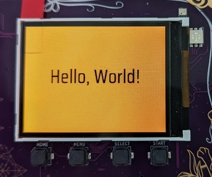
It will take a couple of minutes to download all the components. Once completed, a simple app
showing “Hello, World!” will run on your badge.
Difference to “normal” IDF
If you have previously used the IDF, you may have noticed that we don’t use idf.py flash to
install the app on the Badge. (And if you haven’t, you can safely skip this section. :)
The idf.py flash command assumes that the binary to flash is the main
application for the device. This is not the case for the Badge, though. The
main application is the
launcher app, i.e. the
app with the menu that starts by default. The make install target of the
Makefile copies our newly created app into the
appfs
instead of overwrting the launch. Once copied to the appfs, the launcher can
find it and the app should appear in the apps menu.
Obviously you can use idf.py flash but you’ll delete the launcher
app and would need to reinstall it later.
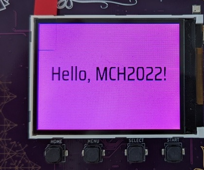
Customizing the template app
Finally! Now that we have all the bureaucracy taken care of, we’ll start off by
modifying the message printed to the screen. Have a look at this
line
of main.c, you can see the text shown on screen:
//...
        // This text is shown on screen.
        char             *text = "Hello, World!";
//...
This part is responsible for drawing the text to the screen.
Go ahead and try to edit the text, here shown as “Fancy App!”:
The buttons on the Badge are not directly connected to the ESP32, instead they
are read by the rp2040 coprocessor via I2C. Have a look in the
esp32-component-mch2022-rp2040
component in case you are interested in the details.
The button handler starting on this
line
of main.c currently causes the app to exit and return to the launcher
whenever the HOME button is pressed.:
        //...
        // Await any button press and do another cycle.
        // Structure used to receive data.
        rp2040_input_message_t message;
        // Await forever (because of portMAX_DELAY), a button press.
        xQueueReceive(buttonQueue, &message, portMAX_DELAY);

        // Is the home button currently pressed?
        if (message.input == RP2040_INPUT_BUTTON_HOME && message.state) {
            // If home is pressed, exit to launcher.
            exit_to_launcher();
        }
        // Is the home button currently pressed?
        if (message.input == RP2040_INPUT_BUTTON_HOME && message.state) {
            // If home is pressed, exit to launcher.
            exit_to_launcher();
        }
        //...
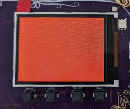
Let’s change this behaviour so the screen is briefly pink after pressing the A button.
Graphics for the badge are handled by a library called Pax, if you want to dig deeper
have a look at the docs here
Pax uses the same RGB (well, ARGB, to be precise) hex triplets as HTML.
0xeb34cf is beautiful MCH pink.
//...
        // Button handling.
        if (message.input == RP2040_INPUT_BUTTON_ACCEPT && message.state) {
                // Make a pink background.
                pax_background(&buf, 0xeb34cf);
                // Update the screen.
                disp_flush();
                // Wait for half a second.
                vTaskDelay(pdMS_TO_TICKS(500));
                // After this, it loops again with a new random background color.
        } else if (message.input == RP2040_INPUT_BUTTON_HOME && message.state) {
            // If home is pressed, exit to launcher.
            exit_to_launcher();
        }
//...
Using WiFi
The template app you’ve been playing with has a simple WiFi connection
API.
First, empty the while loop so it looks like this:
//...
    while (1) {
        // Await any button press and do another cycle.
        // Structure used to receive data.
        rp2040_input_message_t message;
        // Await forever (because of portMAX_DELAY), a button press.
        xQueueReceive(buttonQueue, &message, portMAX_DELAY);

        // Is the home button currently pressed?
        if (message.input == RP2040_INPUT_BUTTON_HOME && message.state) {
            // If home is pressed, exit to launcher.
            exit_to_launcher();
        }
    }
//...
Instead of writing “Hello World” to the screen, we will modify the code to
change the background color to indicate our Wifi connection status. Call
wifi_connect_to_stored() to connect to WiFi and set the background color
depending on whether the function returned successfully.
//...
    // Init (but not connect to) WiFi.
    wifi_init();
    // Now, connect to WiFi using the stored settings.
    bool success = wifi_connect_to_stored();
    if (success) {
        // Green color if connected successfully.
        pax_background(&buf, 0xff00ff00);
    } else {
        // Red color if not connected.
        pax_background(&buf, 0xffff0000);
    }
    disp_flush();
//...
What you want to do with WiFi varies a lot, so we can’t explain that here. But
if you have other libraries that need WiFi (for example an MQTT client), you
start them after this code.
Sharing is caring!
Now you’re ready to publish your app in the Hatchery. Follow these instructions to publish your app.
For further information:
2 - A More Advanced Example
If you have reached this page, you have probably already had a look at the
template app and played
through the getting started tutorial. If not, it
might be a good idea to do it now - there’s a lot of information on getting the
prerequisites installed.
You will need a computer with libusb, pyusb, git, cmake, make, python3, a
terminal, a web browser and a text editor. This should be easily doable on
Linux machines and Macs - if you’re on Windows, it’s probably easiest to work
in a Linux wrapper but YMMV. Additionally, a github account is helpful but not
strictly needed. Check here for details.
This journey assumes that you have some basic familiarity with shell, C and git
(or a search engine of your choice). This is not a line-by-line tutorial, it
just gives you the rough outline of writing an app and discusses some
approaches and techniques along the way. If you want to cheat and download the
finished project, go here
Starting
Start by cloning the template
app - go there, click on
“Use this template” and follow the instructions to make your own copy (or you
can clone the repo and add a new remote manually). git clone the repo,
cd to it and run make prepare. This should set up the ESP-IDF and
all badge-specific components.
What should we do?
If you’re not sure what you want to hack, the ESP-IDF examples are an
amazing starting point. They are already on your machine: ls esp-idf/examples.
Hours of happy browsing. Besides covering many features of the ESP32, they are
exceptionally well written and documented (usually).
We’ll use one of these app to build our app - something that can’t be done in
the BadgePython world: Let’s turn the Badge into a bluetooth Boom Box. Speaker
sound quality will most likely be worse than any smartphone on this planet,
but with the headphone output, this thing might even be usable for something.
There’s a working example at
esp-idf/examples/bluetooth/bluedroid/classic_bt/a2dp_sink.
The code example already shows how to hook the audio stream to an I2S
(Inter-IC
Sound)
DAC. And conveniently, the Badge’s audio outputs are connected to an I2S DAC!
Almost like we’re done already before we even started.
Shameless Copying
To get started, copy the following files from the IDF project’s main directory:
bt_app_av.h, bt_app_av.c, bt_app_core.h, bt_app_core.c into your own
main folder (they are Public Domain, after all!). And while you’re at it,
copy most of the contents of the main.c file over to the end of your main.c
file and the includes to the top.
Actually Hacking Some Code …
Start by integrating the bluetooth initialization routine into your app. Rename
the bluetooth example’s app_main to bt_init and call it within our
app_mainfunction in place of the call to wifi_init ( we won’t be
using WIFI in this example). bt_init must be declarated above app_main
code. Either move the whole function up, or add a declaration.
Unfortunately, both app_main and bt_init call nvs_flash_init.
And nvs_flash_init may only be called once. Get rid of the second
call.
The example projects defines a number of constants using menuconfig. These
are defined in
Kconfig.projbuild,
but we don’t need them. For example, this mechanism in the original IDF example
allows you to redefine the I2S pins to use, but these are hardwired on the
Badge, so configuring them adds unnecessary complexity. grep through main.c
looking for CONFIG_EXAMPLE and replace them:
CONFIG_EXAMPLE_A2DP_SINK_OUTPUT_INTERNAL_DAC : should be false, this option would route the audio to the ESP’s internal DAC, but the Badge has a dedicated audio DAC chipCONFIG_EXAMPLE_I2S_BCK_PINCONFIG_EXAMPLE_I2S_LRCK_PINCONFIG_EXAMPLE_I2S_DATA_PIN
We need to find the new values for the I2S pins
CONFIG_EXAMPLE_I2S_BCK_PIN, CONFIG_EXAMPLE_I2S_LRCK_PIN and
CONFIG_EXAMPLE_I2S_DATA_PIN in i2s_pin_config_t. Obviously, you can
find the pins in the hardware
schematics,
but there’s an easier way: Have a look at
components/mch2022-bsp/include/mch2022_badge.h.
The Badge’s board support package has defines for all pins. (Note: At time of
writing, this header had LRCLK and BCLK swapped, but hopefully this will be
sorted out soon).
The components directory is generally a good place to look if you’re
looking for Badge drivers. All items in this folder are independent components.
You can imagine them as libraries. They are automatically added to the project
by the ESP-IDF build system.
I2S has some sloppy signal naming rules, which may be confusing. LR is LRCLK (a
word clock), CLK is BCK (a bit clock) and DATA is DATA. In addition, our DAC
wants a MCLK (usually faster than the bit clock), so we add an entry:
.mck_io_num = GPIO_I2S_MCLK. In the end, it should look something like
this:
    i2s_pin_config_t pin_config = {
      .mck_io_num = GPIO_I2S_MCLK,
      .bck_io_num = 4, // should be GPIO_I2S_CLK
      .ws_io_num = 12, // should be GPIO_I2S_LR
      .data_out_num = GPIO_I2S_DATA,
      .data_in_num = -1 // not used
    };
    i2s_set_pin(0, &pin_config);
While you’re at it, you can tweak the I2S parameters to our needs (located directly
above the pin_config code). I2S has half a dozen different dialects and
each I2C peripheral speaks a different one. Getting the parameters right is not
hard but tedious, requiring comparison of
datasheets. Additionally, because
the I2S peripheral will stream audio data via DMA, we can adjust buffer
sizes. Here’s some settings that seem to work well:
    i2s_config_t i2s_config = {
      .mode = I2S_MODE_MASTER | I2S_MODE_TX, // TX only
      .sample_rate = 44100,
      .bits_per_sample = I2S_BITS_PER_SAMPLE_16BIT,
      .channel_format = I2S_CHANNEL_FMT_RIGHT_LEFT, // stereo
      .communication_format = I2S_COMM_FORMAT_STAND_I2S,
      .dma_buf_count = 6,
      .dma_buf_len = 128,
      .intr_alloc_flags = 0, // default interrupt priority
      .bits_per_chan = I2S_BITS_PER_SAMPLE_16BIT,
      .tx_desc_auto_clear = true // auto clear tx descriptor on underflow
    };
    i2s_driver_install(0, &i2s_config, 0, NULL);
Almost Ready to Try
We’re close to getting something working. Just four things before we try our first build:
- Change our app name: The projects Makefile contains an
install target.
It’s purpose is to push the project’s binary to the Badge during development.
The name in quotes is the name shown on the Badge’s app chooser. Change it
something unique. - Change the Speaker’s name: There’s a
#define that we copied over from
the bluetooth example: LOCAL_DEVICE_NAME. This is the name broadcast
via bluetooth. Change it to something unique. idf.py menuconfig: menuconfig allows you to enable and configure the
components in your project. First, enable bluetooth. Start the tool with
make menuconfig, go to Component config > Bluetooth and enable it.
Go to Bluedroid Options and enable Classic Bluetooth and
A2DP(Advanced Audio Distribution Profile = what bluetooth speakers do).
Later on, menuconfig is a good place to disable unneeded software
components. For now, we don’t care.- Add files to compile: Remember that we added additional ‘*.c’ files,
bt_app_av.c and bt_app_core.c? The project’s build process works
roughly as follows: make build triggers idf.py build which in
turn uses cmake. For now you don’t need to understand this in
detail,you just have to tell the build system about the new files. We need to
edit main/CMakeLists.txt. When you’re done, the SRCS section
should look something like this:
    SRCS
        "main.c"
        "bt_app_core.c"
        "bt_app_av.c"
Now it’s time to make. Type make prepare, this downloads all the
prerequisite tools and code. This process might take a while. It will fell like
an eternity. Meanwhile, whistle the Jeopary theme song. Drink some water. Wash
your hands. Give a polite, honest compliment to a stranger.
The make process should have finished by now. Now type make build. If this
fails, you probably didn’t follow the steps properly (most likely the
compliment part). No worries, subsequent builds will be faster.
Now, run make install. If there’s an error concerning missing USB, repeat the
libusb and pyusb install steps. If you get a
UnicodeEncodeError in printProgressBar, you’re using a Mac and you
can solve this problem by editing tools/webusb.py: Replace the fill
character with another character, e.g. *. Or fix it and create your first PR
to the tools repo!
If everything went as expected, you should see a WebUSB screen on the Badge and
a progress bar in the terminal. Once upload and verification completes, the
Badge should reboot and show the “Hello world” screen of the template app.
… Boring!
Take your phone or other bluetooth device, scan for new devices. Select
BadgeBoomBox or whatever you chose for your speaker’s name and pair them.
Make sure the speaker switch on your Badge is turned on. Play some music. Hear
it? That amazing sound of no bass? Unbelievable.
Understand What’s Going On
Good work! Let’s take a short break and look at what the app is doing (hey,
we didn’t write much of it yet). ESP-IDF has a logging
facility
that is used in the example code (look for ESP_LOGI, ESP_LOGE,
ESP_LOGD etc.). We can monitor the logs with make monitor (if it
does not work, you might want to set the PORT environment variable to the ESP’s
/dev/tty* ). If you succeed, you will see bluetooth connection and
disconnection events and all sorts of interesting things happening. For
example:
There are “volume change simulation” events. Too bad we didn’t look into the
example before - the example code simulates volume controls and a user
randomly turning the volume up and down to showcase the AVRC (Audio/Video
Remote Control) features. This has to go. But just the “random volume change”
part - we may want to hook the volume control to our
buttons. The simulation is executed in a separate task, look for
s_vcs_task_hdl in bt_app_av.c and surgically remove it from the
source code along with volume_change_simulation.
If you connected specific devices, e.g. an Android phone, you might be
surprised to see that the phone will not only send connect/disconnect and
play/pause events, but sometimes also track titles as well as album and
artist names. Wouldn’t it be great to see this on the screen?
AVRC is not consistently used by all devices. Some features are used, some not.
Anyway, let’s have some fun with it.
Another nice thing to have would be a dB-Meter. Our next task is to sift through
the code to see where the audio stream passes by to analyze it.
Side note: Tasks, Events, FreeRTOS messaging and our threading approach
ESP-IDF makes heavy use of FreeRTOS. Two essential building blocks of FreeRTOS
are Tasks and Queues. Tasks can be seen as threads: Independent,
preemptively scheduled sequences of operation. Each application has a main
thread (the one that executes app_main), a timer thread and possibly other
threads (e.g. for bluetooth, Networking and other things). Queues are often
used to pass events and other information from one task to another. They are
basically thread-safe FIFO buffers. One task (or an interrupt) posts elements
into the queue and another task can wait for elements to arrive in that queue.
The template app already uses one queue: The RP2040 firmware will post
button presses into this queue. The application’s main loop waits for button press
events to arrive and reacts to it by setting a new random color and redrawing
the screen.
The bluetooth stack uses its own tasks. Our task, the main task, controls the
screen and user interaction (and it’s a good idea to restrict this to a single
task). So if we want to receive bluetooth information in the main task, it’s a
good idea to use a queue. bluetooth event -> queue -> main task
reacts.
But our main task is already blocked waiting for the button press queue! How
can we receive our Bluethooth events? Could we use the button queue for our
bluetooth events? Yes you could! But it’s not polite to push things into
other’s queues without prior consent. So we don’t.
There’s another option: Queue sets are used to combine queues and
(other things) and wait on several events simultaneously.
So we’ll create a new audioQueue to send us messages whenever there’s
a relevant bluetooth and/or audio event. We also use this queue to send
audio level updates regularly.
Queue entries can have data attached to them. This is often a struct with an
event type and additional data, typically implemented as a union so that
different events can have different data associated with them. It’s good
practice to keep these entries short because queues will have to allocate
several instances prior to usage (Real Time OSes prefer allocating a fixed
amount of memory at start instead of dynamically allocating memory during
runtime).
To keep the queued data short, we will not include the full audio stack state
in the queue entries. Instead we’ll generate an event to notify that the state changed, but
not what actually changed. For this, we use another mechanism to get data
safely from one task to another: Semaphores used as mutexes / locks. The
bluetooth stack will collect its own state in a struct. The main task can
request a copy of that state struct. All accesses to members of that struct
will be embedded in a lock, making sure that only one task has access to this
struct at any instance in time.
Queues are good for pushing information from one task to another, mutexes are
good for pulling. Admittedly, we could have used just queues in this case, but
this example is supposed to be at least slightly educational…
In addition to the “something changed in the bluetooth audio state” event, we
will have a dB-Meter-update event that should be sent in roughly 20-50Hz
intervals so that we can have a smooth noise meter animation.
Who should manage the queue? The queue could be located either in the
bt_app_*** part or in our main.c. Both are good options. We will
add them to main.c, reasoning that the bt_app_*** is a generic service
and should not make any assumptions about hosting application. As a
consequence, the bt_app_*** part will just issue callbacks whenever
something interesting happens. The code we’ll write in main.c takes care
of queueing these events.
We will leave the well-paved path of documenting every changed part in the code
here. The remaining document will show some examples. As said, the full code is
in the repository.
After some light reading, you’ll quickly get a better overview over the
bluetooth app: naming suggest that bt_app_core.c seems to do the actual
streaming while bt_app_av.c handles metadata and remote control. So the
audio data is more likely to be found in bt_app_core.c. And metadata is
most likely found in bt_app_av.c.
We need to decide: What data is useful for us? What could
we want to display?
- Connection state: Whether we’re disconnected, connected, connecting or
disconnecting
- Audio playback state: Whether we’re playing, stopped or suspended (which is,
in effect, also stopped somehow)
- The current volume: A value between 0..127
- Our current sample rate (no idea if someone is interested but anyway, let’s
collect it)
- Current title, artist and album (if available)
So a simple struct to hold that state should look something like this:
/** the full exposed audio state in a struct */
#define AUDIOSTATE_STRLEN 100
typedef struct BTAudioState_ {
  esp_a2d_connection_state_t connectionState;  // 0=disconnected, 1=connecting, 2=connected, 3=disconnecting
  esp_a2d_audio_state_t playState;  //0=suspended, 1=stopped, 2=playing
  uint8_t volume; //0..127
  int sampleRate;
  char title[AUDIOSTATE_STRLEN];
  char artist[AUDIOSTATE_STRLEN];
  char album[AUDIOSTATE_STRLEN];
} BTAudioState;
So what do we do now? Look into the logs (remember make monitor) for the data
we’re interested in. Find the code that generated the log messsage. Insert
code to update our state. Be sure to lock each access to the struct. After a
change, push an entry to the event queue. It’s a good idea to clear the state
when we get disconnected.
For example, we insert four lines to handle ESP_A2D_AUDIO_STATE_EVT,
an event sent whenever the actual stream is started, stopped or suspended:
    case ESP_A2D_AUDIO_STATE_EVT: {
        a2d = (esp_a2d_cb_param_t *)(p_param);
        ESP_LOGI(BT_AV_TAG, "A2DP audio state: %s", s_a2d_audio_state_str[a2d->audio_stat.state]);
        s_audio_state = a2d->audio_stat.state;
        if (ESP_A2D_AUDIO_STATE_STARTED == a2d->audio_stat.state) {
            s_pkt_cnt = 0;
        }
        lockAudioState();
        audioState.playState = a2d->audio_stat.state;
        unlockAudioState();
        notifyAudioStateChange();
        break;
    }
There are other parts where the state is updated, but they all follow the same
principle, so it would be boring to list them all here. Try yourself! Or have a
look at the repo. lockAudioState()acquires the lock,
unlockAudioState() releases it and notifyAudioStateChang() pushes
an event to our queue.
Tapping the audio stream
bt_app_core.c has two tasks: The bt_app_task that responds to
bluetooth stuff and the bt_i2s_task that seems to stream the audio data
to the I2S peripheral. Bingo! That’s ideal!
Have a look at bt_i2s_task_handler: This function mainly consists of an
endless loop waiting on a ring buffer to deliver sample data and pushes
that data into the i2s peripheral. We can hack that! First, we want to
implement volume control by scaling each sample. Second, we want to calculate
the audio volume. Have a look:
static void bt_i2s_task_handler(void *arg) {
    uint8_t *data = NULL;
    size_t item_size = 0;
    size_t bytes_written = 0;
    static float leftSquares = 0;
    static float rightSquares = 0;
    static int sampleCount = 0;

    for (;;) {
        /* receive data from ringbuffer and write it to I2S DMA transmit buffer */
        data = (uint8_t *)xRingbufferReceive(s_ringbuf_i2s, &item_size, (portTickType)portMAX_DELAY);
        if (item_size != 0){
            int16_t *buf = (int16_t*)data;
            int numSamples = item_size / 2;
            uint8_t vol = getVolume();
            float volScale = volumeScale[vol] / 65536.0f;
            // Sample processing can go here. Right now, only volume scaling and RMS analysis
            for (int i=0; i<numSamples; i += 2) {
                float l = (float)buf[i];
                l *= volScale;
                leftSquares += l*l;
                buf[i] = l;
                float r = (float)buf[i+1];
                r *= volScale;
                rightSquares += r*r;
                buf[i+1] = r;
            }
            sampleCount += numSamples;
            i2s_write(0, data, item_size, &bytes_written, portMAX_DELAY);
            vRingbufferReturnItem(s_ringbuf_i2s, (void *)data);
            if (sampleCount >= 1500) {
              notifyAudioRMS(sqrtf(leftSquares / sampleCount), sqrtf(rightSquares / sampleCount));
              leftSquares = 0;
              rightSquares = 0;
              sampleCount = 0;
            }
        }
    }
}
This code is by no means elegant nor efficient. First, we cast the data buffer
to an int16 array (we know that we have 16 bit samples and I2S has them
typically interleaved, L/R/L/R/…). For each buffer, we request the current
audio volume, get a scaling factor via a lookup table (perceived volume is
logarithmic). Then we go through all left and right samples, convert each to
float and multiply it with our volume factor. Then we convert the sample back
to int and replace the sample in the buffer with our scaled value.
We also square each sample and sum the squares for the left and right channel.
After 1500 samples (roughly every 30ms for 44KHz), we divide the the sum of
squares by the number of samples, resulting in the mean square, and then take
the square root, resulting in the Root of the Mean Square (RMS).
That’s a good basis for a volume display. notifyAudioRMS() will push an
audio RMS update to the event queue. After reporting, we reset the accumulators
for the next interval.
Converting everything to float and back is terribly unneccessary and terribly
slow. But the ESP is fast enough and this is a good starting point for further
DSP (anyone?).
Bring it together
Now that we have extended the bluetooth audio code to give us callbacks
whenever something happens, it’s time to bring it all to the main loop. Let’s
see what we should do in the main loop:
- Audio state changed: Pull audio state, redraw screen
- Audio RMS levels changed: Remember levels, redraw just the level meter
- Home button pressed: Exit to launcher
- Joystick up or down: Increase or decrease volume, redraw all
First, write typedefs and structs that can hold audio events (state changes or
RMS updates):
typedef enum BTAudioEventType_ {
  Event_StateChanged = 1, ///< audio state has changed, may be queried using getAudioState
  Event_RMSUpdate        ///< audio RMS update
} BTAudioEventType;

typedef struct BTAudioEvent_ {
  BTAudioEventType type;
  union {
    struct {
      float left;
      float right;
    } rms;
  } data;
} BTAudioEvent;
Next generate a queue to hold these events:
audioQueue = xQueueCreate( 10, sizeof(BTAudioEvent) );
Now we need callback functions to call from the bluetooth part (running in
the the bluetooth task!). Their purpose is to push a BTAudioEvent into the
audioQueue:
/** callback from bt_app_av: state has changed */
void audioStateChange() {
  BTAudioEvent evt = {
    .type = Event_StateChanged
  };
  xQueueSend(audioQueue, &evt, 0);  //evt is copied to queue
}

/** callback from bt_app_core: new volume measurement */
void audioRMSUpdate(float left, float right) {
  BTAudioEvent evt;
  evt.type = Event_RMSUpdate;
  evt.data.rms.left = left;
  evt.data.rms.right = right;
  xQueueSend(audioQueue, &evt, 0); //evt is copied to queue
}
Next, register the callbacks (not shown: They will just be stored in global
variables and called when necessary)
  setAudioStateChangeCB(&audioStateChange);
  setAudioRmsCB(&audioRMSUpdate);
At this point, updates from the bluetooth stack will end up in our
audioQueue. Time to combine the queues:
  QueueSetHandle_t queueSet = xQueueCreateSet(20);
  xQueueAddToSet(buttonQueue, queueSet);
  xQueueAddToSet(audioQueue, queueSet);
Finally, we can write our main event loop:
  while (1) { //handle events from both button and audio queue
    QueueSetMemberHandle_t queue = xQueueSelectFromSet(queueSet, portMAX_DELAY);
    if (queue == buttonQueue) {
      rp2040_input_message_t message;
      xQueueReceive(buttonQueue, &message, 0);
      if (message.state) {
        switch(message.input) {
          case RP2040_INPUT_BUTTON_HOME:
            exit_to_launcher();
            break;
          case RP2040_INPUT_JOYSTICK_UP:
            volume_set_by_local_host(audioState.volume < 122 ? (audioState.volume+5) : 127);
            drawAll();
            break;
          case RP2040_INPUT_JOYSTICK_DOWN:
            volume_set_by_local_host(audioState.volume > 5 ? (audioState.volume-5) : 0);
            drawAll();
            break;

        }
      }
    } else if (queue == audioQueue) { //audio event
      BTAudioEvent evt;
      xQueueReceive(audioQueue, &evt, 0);
      if (evt.type == Event_StateChanged) { //state changed: update main UI
        getAudioState(&audioState);
        drawAll();
      } else if (evt.type == Event_RMSUpdate) {  //RMS: Update bars
        float leftDB = 20 * log10(evt.data.rms.left);
        float rightDB = 20 * log10(evt.data.rms.right);
        leftDBMeter = (leftDB - DBMETER_MIN) / (DBMETER_MAX - DBMETER_MIN);
        rightDBMeter = (rightDB - DBMETER_MIN) / (DBMETER_MAX - DBMETER_MIN);
        drawDBMeter();
      }
    }
  }
The xQueueSelectFromSet will wait until am event arrives in one of the
queues and return which queue was active. The rest is dispatch: If the origin
was the button queue, react to button or joystick input. If it was an audio
event, redraw the level meter or the whole screen. The RMS update will convert
the RMS to dB by calculating the logarithm (as said above, perceived volume is
logarithmic). Then, the values will be scaled to fill the screen. The values
DBMETER_MIN and DBMETER_MAX are arbitrarily chosen so that the
level meter shows something useful.
Show it!
We’ve put some effort into collecting and merging data to display. Now it’s
time to visualize the data. The Badge comes with a convenient graphics
package that allows us to draw shapes and write text. It
draws to a bitmap and then transfers the bitmap to the screen. Currently, the
transfer to screen is not very fast as it uses the MCU to control the transfer
(anyone interested in implementing DMA transfers? Pull Request, plz!). Smooth
fullscreen animations will be difficult. However, it’s possible to just
transfer parts of the buffer. The only smooth animation we need is the level
meter.
For simplicity, let’s draw that as a horizontal bar graph (expanding to the
left and right from center for the left and right channel) at the bottom of the
screen and put it in a separate drawing function, drawDBMeter(). The
remaining screen is drawn in drawAll(), which will, in turn, call
drawDBMeter(). This way we can either update the DB graph quickly or the
whole screen slowly. Both functions will transfer their parts to the screen.
void drawDBMeter() {
  if ((audioState.connectionState != ESP_A2D_CONNECTION_STATE_CONNECTED) || (audioState.playState != ESP_A2D_AUDIO_STATE_STARTED)) {
    leftDBMeter = 0;
    rightDBMeter = 0;
  }
  int halfWidth = (ILI9341_WIDTH / 2);
  float l = (leftDBMeter < 0) ? 0 : (leftDBMeter > 1) ? 1 : leftDBMeter;
  float r = (rightDBMeter < 0) ? 0 : (rightDBMeter > 1) ? 1 : rightDBMeter;
  int leftPix = halfWidth * l;
  int rightPix = halfWidth * r;
  int p1 = halfWidth - leftPix;
  int p2 = halfWidth + rightPix;
  int y = ILI9341_HEIGHT-DBMETER_HEIGHT;
  pax_col_t bgCol = pax_col_rgb(0,0,0);
  pax_col_t fgCol = pax_col_rgb(255,255,255);
  pax_simple_rect(&screenBuf, bgCol, 0,  y, p1, DBMETER_HEIGHT);
  pax_simple_rect(&screenBuf, fgCol, p1, y, p2-p1, DBMETER_HEIGHT);
  pax_simple_rect(&screenBuf, bgCol, p2, y, ILI9341_WIDTH-p2, DBMETER_HEIGHT);
  int off = 2 * ILI9341_WIDTH * (ILI9341_HEIGHT-DBMETER_HEIGHT);
  ili9341_write_partial_direct(get_ili9341(), screenBuf.buf+off, 0, ILI9341_HEIGHT-DBMETER_HEIGHT, ILI9341_WIDTH, DBMETER_HEIGHT);
}
The code relies on the audioState struct and the leftDBMeter and rightDBMeter variables
(all are local to the main task, so we don’t need to worry about threading
here). DBMETER_HEIGHT is a global variable determining the height of the
bar in pixels and ILI9341_WIDTH and ILI9341_HEIGHT are variables
defined in the display driver component included with the template app. Drawing
is pretty straightforward:
- If we’re currently not playing music, the meter should be at zero
- Levels are clamped and then scaled to screen size
- The bar graph always consists of a white rectangle in the middle and two
black rectangles at the sides. It would be slightly easier to fill the whole
area black and then a white rectangle over it, but that would touch some
pixels twice. The three-rectangles-approach only sets each pixel once.
- In the end, the
ili9341_write_partial_direct() call transfers the
screen portion of the bar graph to the screen.
The drawAll() function is longer but even easier:
void drawAll() {
  static const char disconnected[] = "Disconnected";
  static const char connecting[] = "Connecting...";
  static const char disconnecting[] = "Disconnecting...";
  static const char stopped[] = "Stopped";
  static const char playing[] = "Playing";

  pax_col_t bgCol = pax_col_rgb(0,0,0);
  pax_background(&screenBuf, bgCol);

  pax_col_t fontColor = pax_col_rgb(255,255,255);
  const char *status = "?";
  switch (audioState.connectionState) {
    case ESP_A2D_CONNECTION_STATE_CONNECTING:
      status = connecting;
      break;
    case ESP_A2D_CONNECTION_STATE_DISCONNECTING:
      status = disconnecting;
      break;
    case ESP_A2D_CONNECTION_STATE_DISCONNECTED:
      status = disconnected;
      break;
    case ESP_A2D_CONNECTION_STATE_CONNECTED:
      status = (audioState.playState == ESP_A2D_AUDIO_STATE_STARTED) ? playing : stopped;
  }

  char volStr[30];
  snprintf(volStr, 30, "Volume: %i%%",audioState.volume * 100 / 127);

  pax_draw_text(&screenBuf, fontColor, pax_font_saira_condensed, pax_font_saira_condensed->default_size, 10, 10, status);
  pax_draw_text(&screenBuf, fontColor, pax_font_saira_regular, pax_font_saira_regular->default_size, 10, 90, audioState.title);
  pax_draw_text(&screenBuf, fontColor, pax_font_saira_regular, pax_font_saira_regular->default_size, 10, 115, audioState.artist);
  pax_draw_text(&screenBuf, fontColor, pax_font_saira_regular, pax_font_saira_regular->default_size, 10, 140, audioState.album);
  pax_draw_text(&screenBuf, fontColor, pax_font_saira_regular, pax_font_saira_regular->default_size, 10, 165, volStr);

  ili9341_write_partial_direct(get_ili9341(), screenBuf.buf, 0, 0, ILI9341_WIDTH, ILI9341_HEIGHT-DBMETER_HEIGHT);
  drawDBMeter();
}
The function just clears the screen and then writes some text to it. Most of
the code just determines the message to draw.
ili9341_write_partial_direct() transfers everything except for the volume
meter and calls drawDBMeter() to update that part.
This should be it. Make and install again (and, if needed, debug, rinse,
repeat). There should be awesome sound and an awesome user interface.
Publishing
The Badge.team hatchery also allows publishing native apps. Go to The Hatchery,
register, login. There should be an option to publish native ESP32 apps. This
tutorial is already way to long, though. Follow these instructions if you want
to publish your app in The Hatchery
3 - ESP-IDF fancy name tag
There are endless games and apps to explore on the badge, but when going about your business on the camp, most likely its main function will be a name tag. So what better than writing a custom name tag to show off your style, identity, hacker skills, memes, or whatever you want.
After having completed the getting started you should have a template app that can draw a colored background and some text. Change the text to your name, and you have yourself a name tag… right? Let’s explore some ways in which you can spice up your name tag.
Other drawing functions
The pax-graphics documentation has quite a nice list of all the fonts and drawing primitives it contains.
Drawing lines and circles may sound a bit boring, but if you duck “line patterns” or “geometric pattern” or similar queries you can find quite some nice patterns to draw with those basic shapes.
In addition I’d like to draw your attention to the shaders documentation which has a nice example to draw rainbows on shapes, which you could easily adapt to do all sorts of nice gradients.
Drawing images
Geomeric patterns are nice, but if you want to show off your art, the logo of your favourite retrocomputer, a character from your favourite franchise, or your favourite meme, you’ll want to load images onto the screen.
The pax-graphics side of drawing images is well documented. But before you get to that point, there are a few things you need to do.
Of course first you need to find or make an image. This part is up to you. Keep in mind that the badge screen is 320x240 pixels, and that pax-graphics only loads png.
Next you’ll need to get the image onto the badge. Since internal flash space is extremely limited, it’s highly recommended to use a micro SD card. Be careful when inserting it! To push the png image to the SD card:
python3 tools/webusb_fat_push.py myimg.png /sdcard/myimg.png
To use the SD card, you need to include the component, and mount it. Then you can open the file.
#include "sdcard.h"

// image buffer
static pax_buf_t myimage;

// mount sd card
esp_err_t res  = mount_sd(GPIO_SD_CMD, GPIO_SD_CLK, GPIO_SD_D0, GPIO_SD_PWR, "/sd", false, 5);
if(res != ESP_OK) ESP_LOGE(TAG, "could not mount SD card");

// open file
FILE* fd = fopen("/sd/myimg.png", "rb");
if(fd == NULL) ESP_LOGE(TAG, "could not open file");

// store as a buffer for later use, best for animations
if(!pax_decode_png_fd(&myimage, fd, PAX_BUF_16_565RGB, 0)) ESP_LOGE(TAG, "could not parse png");
pax_draw_image(&buf, &myimage, x, y);

// or draw directly, simplest for static drawings
if(!pax_insert_png_fd(&buf, fd, x, y, 0)) ESP_LOGE(TAG, "could not parse png");
If you do not have a micro SD card, and you only want to load a small image, you can also mount the internal filesystem instead.
Making animations
An animation is just some static drawings in a row. Once again, it’s what you do with it.
The template app already has an infinite loop that waits forever until a button is pressed. Do not remove that part! The ESP32 is running an RTOS that needs to do some book keeping in the background. Without some delay somewhere you’ll get watchdog timer errors. However, you can change the line to the following, to only wait a few milliseconds instead of forever. Tweak this number to get the frame rate you want, or to make a nice slideshow.
xQueueReceive(butonQueue, &message, pdMS_TO_TICKS(1));
If you can’t get the framerate you want, and are doing a lot of rendering in pax-graphics, you can offload that to the second core for a free speed boost.
If that still isn’t fast enough, you should hop over to the FPGA section, which has a faster parallel bus to the display.
As for what kind of animations to make, a great source of inspiration is demoscene videos. Here is a page that has some implementations of a few of the classic effects, but there are plenty of other cool effects to be found all over the internet. Who’s going to implement Nyan Cat, Bad Apple, old Windows screensavers, and more?
RGB galore
The badge includes a kite of RGB LEDs, which you can do cool blinkenlights with. The API is pretty simple: First you need to enable the power gate to the LEDs, then you init it with the correct output pin, and then you send an array of PWM values.
#include "ws2812.h"

// enable power to the LEDs
gpio_set_direction(GPIO_SD_PWR, GPIO_MODE_OUTPUT);
gpio_set_level(GPIO_SD_PWR, 1);
// initialise them
ws2812_init(GPIO_LED_DATA);
// send data
uint8_t led_red[15] = {0, 0xFF, 0, 0, 0xFF, 0, 0, 0xFF, 0, 0, 0xFF, 0, 0, 0xFF, 0};
ws2812_send_data(led_red, sizeof(led_red));
As an example, here is the kite animation that plays when you start the badge.
Making sound
TODO: There isn’t a nice API for this yet. You can steal some code from the launcher maybe.
Using sensors
TODO: Make some nice example with the BNO055 component